Connecting your Yamaha motorcycle to a diagnostic tool opens up a world of information, allowing you to troubleshoot issues and understand your bike’s performance better. While pre-made Yamaha Obd2 Cables are available, building your own can be a cost-effective solution. This guide provides a step-by-step walkthrough of creating a custom diagnostic harness. Disclaimer: This guide is based on personal experience and may not apply to all Yamaha models. Proceed at your own risk.
Understanding the Yamaha Diagnostic Connector
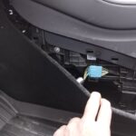
Yamaha motorcycles typically use a 4-pin diagnostic connector. To interface with standard OBD2 diagnostic tools, you’ll need to create a custom cable that bridges the connection. This involves wiring specific pins from an OBD2 connector to the corresponding pins on the Yamaha 4-pin connector.
Gathering Your Tools and Materials
Before you begin, ensure you have the following:
- Wire strippers/cutters: For preparing the wires.
- Needle-nose pliers: For precise wire manipulation.
- Soldering iron (recommended): Provides a more secure connection.
- Molex crimping tool (optional): For crimping the connector pins.
- 4-pin connector: Ensure compatibility with 22-16 AWG wire and 1.3-1.7mm insulation. (Example)
- OBD-II Cable: A standard OBD2 cable with a female connector. (Example)
You can save money by using spare wire if you have some on hand. Remember to choose a 4-pin connector that matches your wire gauge.
Wiring the OBD2 to Yamaha Adapter
This process involves connecting four specific wires from the OBD2 connector to the 4-pin connector.
OBD2 Pin Identification
Only four wires from the OBD2 connector (OBD2C) are needed:
- Pin 4: Chassis Ground (Orange wire)
- Pin 6: CAN High (J-2234) (Green wire)
- Pin 14: CAN Low (J-2234) (Brown with white stripe wire)
- Pin 16: Battery Power (Green with white stripe wire)
Step-by-Step Wiring Instructions
- Prepare the Wires: Strip the outer sheath and shielding from the OBD2 cable, separating the four necessary wires. Secure the remaining wires with a zip tie.
- Prepare the 4-Pin Connector Pins: Strip and twist the ends of the OBD2 wires to increase thickness if necessary. Slide a rubber seal onto each wire.
- Connect the Wires to the Pins: Insert the exposed wire into the first set of prongs on the 4-pin connector pin. Solder or crimp the connection to secure the wire.
- Secure the Seal: Position the rubber seal between the second set of prongs and crimp them down to seal the connection.
-
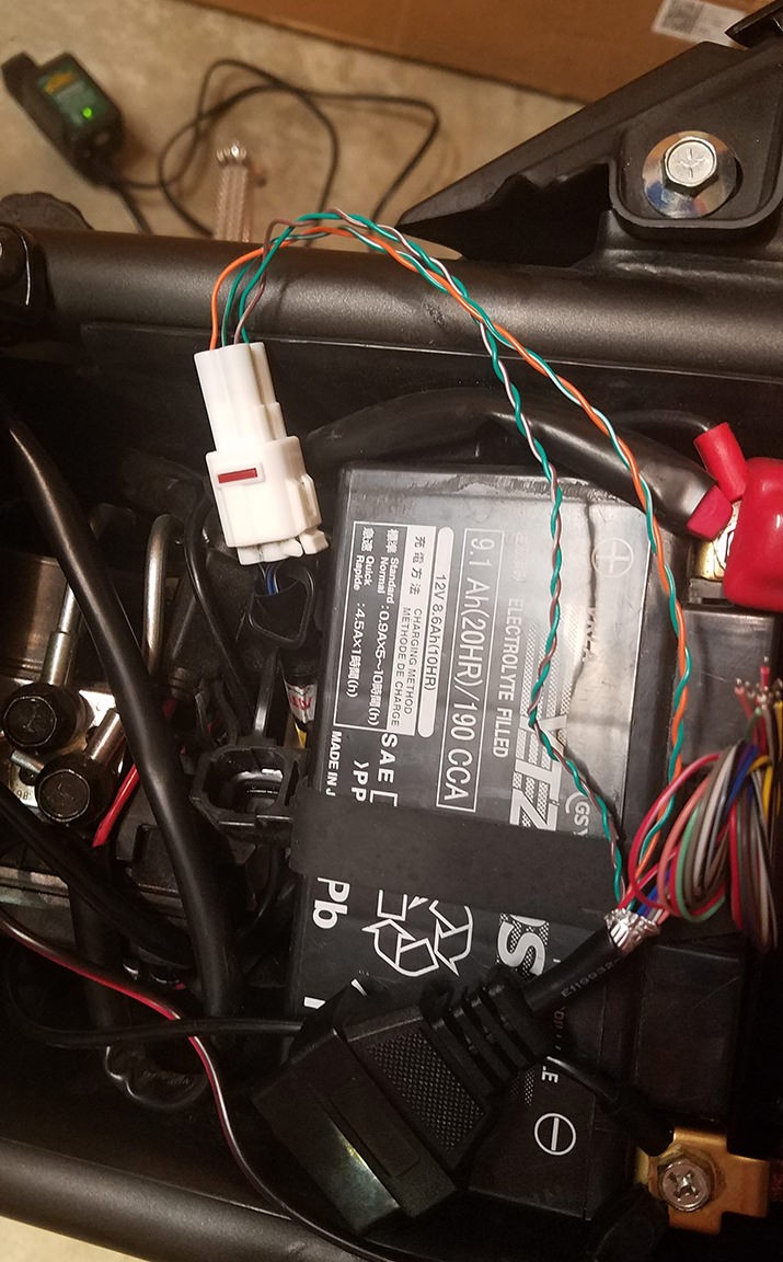
Pair and Twist the Wires: Pair the following wires and twist them together: Pin 4 (orange) with Pin 16 (green/white), and Pin 6 (green) with Pin 14 (brown/white).
-
Connect to the 4-Pin Connector: Insert the pins into the 4-pin connector housing in the following order: Pin 14 (brown/white) into slot A, Pin 6 (green) into slot B, Pin 16 (green/white) into slot C, and Pin 4 (orange) into slot D. Ensure each pin clicks into place.
Testing the Yamaha OBD2 Cable
Once assembled, connect the harness to your Yamaha’s diagnostic port and your OBD2 tool. The successful connection will allow you to read and clear error codes.
This DIY Yamaha OBD2 cable offers a budget-friendly solution for accessing your motorcycle’s diagnostic information. By following these steps, you can create a reliable tool for maintaining and troubleshooting your Yamaha. Remember to double-check your connections and proceed cautiously.