
Connecting a Seeed CAN shield to a vehicle’s OBD2 port via a DB9 connector can be challenging. Many encounter difficulties retrieving data, even with seemingly simple test sketches. This article aims to clarify the Obd2 Db9 connection and provide insights into troubleshooting common issues, focusing on achieving successful communication for custom projects like instrument clusters.
Deciphering the OBD2 DB9 Setup
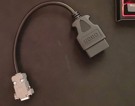
The OBD2 standard utilizes a 16-pin connector, while the Seeed CAN shield often employs a DB9 interface. A custom OBD2 to DB9 cable is required to bridge this gap. Constructing this cable correctly is crucial for successful communication. Commonly, the CAN High (CANH) and CAN Low (CANL) signals from the OBD2 connector are mapped to pins 2 and 3 of the DB9 connector respectively. However, variations exist depending on the specific hardware and application. Always verify the pinout for your specific CAN shield and OBD2 connector. A simple continuity test with a multimeter can confirm accurate wiring.
Troubleshooting Communication Problems
Continuous data transmission without pauses, as observed on an oscilloscope, might indicate an issue with the communication protocol or the request being sent. OBD2 communication operates on a request-response basis. The vehicle’s ECU (Engine Control Unit) should respond only after receiving a valid request. Continuous spamming suggests the ECU isn’t recognizing the requests. This could stem from:
- Incorrect OBD2 DB9 Cable: Double-check the wiring and ensure the correct signals are connected to the corresponding pins. Even a single misplaced wire can disrupt communication.
- Incorrect CAN ID and Message Format: OBD2 utilizes specific CAN IDs and message formats for different requests (PIDs – Parameter IDs). Verify the code is using the correct request ID (0x7DF for standard OBD2 requests) and that the message data is formatted according to the OBD2 standard. This includes the correct mode, PID, and data length.
- Unsupported PIDs: Not all vehicles support all PIDs. Consult your vehicle’s documentation to ensure the requested PIDs (e.g., engine RPM – 0x0C, vehicle speed – 0x0D) are supported.
- CAN Bus Speed: While 500kbps is the standard CAN bus speed for OBD2, some vehicles might use a different speed. Try adjusting the CAN bus speed in your code to match your vehicle’s requirements.
Analyzing the Code Examples
The provided code examples attempt to request data using common OBD2 PIDs. However, they might require adjustments based on the specific hardware and vehicle. Ensure the following:
- Correct Library Usage: The code should utilize the appropriate library for the Seeed CAN shield (e.g.,
mcp_can.h). - Proper Initialization: The CAN bus and the shield should be initialized with the correct settings, including the CAN bus speed and message filtering.
- Accurate Request and Response Handling: The code must send correctly formatted requests and interpret the responses according to the OBD2 protocol. This involves parsing the data bytes to extract the desired information.
Conclusion
Establishing communication between a Seeed CAN shield and a vehicle’s OBD2 port using a custom OBD2 DB9 cable requires careful attention to wiring, communication protocols, and code implementation. Thoroughly verify the OBD2 DB9 cable wiring, ensure the code uses the correct CAN IDs, message formats, and supported PIDs, and adjust the CAN bus speed if necessary. By addressing these potential issues, successful data retrieval for custom projects can be achieved. If problems persist, consult your vehicle’s specific OBD2 documentation and the Seeed CAN shield documentation for further troubleshooting guidance.