
This article explains how to use an MCP2515 CAN controller with an Arduino to request OBD-II data, specifically engine speed (PID 0C). We’ll analyze a provided code example, identify potential issues, and guide you toward a successful implementation.
Understanding the Code and the Problem
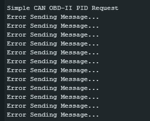
The provided code utilizes an Arduino, an MCP2515 CAN controller, and the OBD-II protocol to request vehicle data. The code attempts to request engine speed (PID 0C) by sending a specific CAN message. However, the returned data indicates an error. Let’s dissect the code and the issue:
Code Breakdown
The code initializes the MCP2515 for CAN communication at 500kbps and sets up filters for specific CAN IDs. It then enters a loop that performs two main functions:
- Reading CAN Messages: When a CAN message is received, the code reads the message ID, data length (DLC), and data bytes. This data is then printed to the serial monitor.
- Sending OBD-II Request: Every second, the code sends a CAN message requesting PID 0C (engine speed). The message is sent to the functional address of the vehicle’s ECU. The crucial part of this request is the
txDataarray:byte txData[] = {0x02, 0x01, 0x0C, 0x55, 0x55, 0x55, 0x55, 0x55};
Let’s break down this txData array:
0x02: Number of bytes in the data field (excluding this byte)0x01: OBD-II service mode (Mode $01 – Current Data)0x0C: Requested PID (Engine Speed)0x55...: Filler bytes (may not be necessary)
The Problem: “NO DATA” Response
The image provided shows a response of “NO DATA” from the OBD-II scanner. This indicates that the vehicle’s ECU either doesn’t support the requested PID or there’s an issue with the request itself. Let’s explore potential reasons for this:
- Incorrect Request Format: While the provided
txDataarray appears correct for a standard OBD-II request, some vehicles might require specific formatting or additional parameters. - Unsupported PID: The vehicle might not support PID 0C. Consult the vehicle’s specific OBD-II documentation.
- CAN Bus Issues: Problems with the CAN bus wiring, termination, or communication speed can prevent successful communication.
- ECU Not Ready: The vehicle’s ECU might not be in a state to respond to OBD-II requests. Ensure the ignition is on and the engine is running.
Troubleshooting and Solutions
Here’s a breakdown of steps to troubleshoot the “NO DATA” response:
- Verify Vehicle Compatibility: Consult your vehicle’s documentation to confirm support for PID 0C and any specific OBD-II requirements.
- Double-Check Wiring and Connections: Ensure all connections between the Arduino, MCP2515, and the OBD-II connector are secure and correctly wired. Verify proper CAN bus termination (typically 120 ohms).
- Test with a Known Working OBD-II Scanner: Using a commercial OBD-II scanner, attempt to read PID 0C. This helps isolate whether the issue is with the vehicle or the Arduino setup.
 OBD-II Connector
- Experiment with Different PIDs: Try requesting other supported PIDs (e.g., vehicle speed, coolant temperature) to confirm basic communication.
- Adjust CAN Bus Speed: Some vehicles might use a different CAN bus speed. Try adjusting the
CAN0.begin()parameters in the code.
Conclusion
Using an MCP2515 with an Arduino to read OBD-II data provides valuable insights into vehicle performance. However, successfully retrieving specific data like engine speed (PID 0C) requires careful attention to request formatting, vehicle compatibility, and proper hardware setup. By systematically troubleshooting potential issues, you can achieve reliable communication and data acquisition.