
A faulty OLED screen prompted a search for a reliable replacement, leading to the discovery of a highly-rated alternative compatible with the Adafruit OLED screen library. This journey also sparked an exploration into the intricacies of OBD2 connections and potential applications for a heads-up display (HUD) project. This article delves into the process of understanding and utilizing an OBD2 extension cable, specifically focusing on identifying crucial pins and exploring the potential of an “Ikkegol Obd2 Driver.”
Understanding the OBD2 Connector
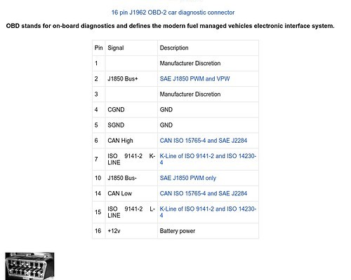
The OBD2 (On-Board Diagnostics) port is a standardized system that allows external devices to access a vehicle’s diagnostic data. To tap into this data stream, a reliable connection is crucial. This project utilizes an OBD2 extension cable, requiring a meticulous examination of its pinout.
For this specific project, five essential pins were identified:
- +12V: Provides power to the connected device.
- Chassis Ground: Ensures a common ground for the electrical system.
- Signal Ground: Provides a ground reference for data signals.
- CAN High: The high-speed CAN (Controller Area Network) data line. This is crucial for communicating with modern vehicle systems.
- CAN Low: The low-speed CAN data line. This line complements the CAN High line for balanced data transmission. This is where the “ikkegol obd2 driver” could potentially come into play.
Identifying and Labeling Essential Pins
Using a multimeter, each wire in the OBD2 extension cable was meticulously tested to determine its corresponding pin on the connector. Once identified, each wire was labeled for clarity and ease of future connections. This meticulous approach minimizes the risk of errors and ensures a reliable connection to the vehicle’s OBD2 port.
Exploring Potential HUD Applications
Research led to the discovery of scope lens protectors used on firearms. These small, transparent pieces mounted on rails could potentially be repurposed for a HUD system, projecting information onto the driver’s field of view.
Next Steps and Future Considerations
The next crucial steps involve connecting the modified OBD2 extension cable to the vehicle’s OBD2 port and verifying the accuracy of the pin identification. Additionally, the new OLED screen will undergo thorough testing to ensure its functionality. Further research will focus on the “ikkegol obd2 driver” and its potential role in facilitating communication between the OBD2 port and the microcontroller. This will be essential for retrieving and displaying vehicle data effectively. This exploration promises to unlock valuable insights into vehicle diagnostics and pave the way for innovative applications in the realm of automotive technology.