This guide provides a detailed walkthrough for creating your own OBD2 to USB wiring harness. This allows you to connect your vehicle’s OBD2 port to a computer for diagnostics. This is a DIY project, and you are responsible for your own actions and results.
Tools:
- Wire strippers/cutters
- Needle-nose pliers
- Soldering iron (recommended)
- Molex crimping tool (optional)
Parts:
- 4-pin connector (22-16 AWG wire size, 1.3-1.7mm insulation/seal size) We used this one: link to part used
- OBD-II Cable (We used this one: link to part used)
You can save money if you have spare wire by purchasing just a female OBD-II connector and the 4-pin connector. Make sure the 4-pin connector matches your wire gauge.
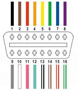
OBD2 Pinout for this Project
This project utilizes only four of the sixteen wires in a standard OBD2 connector (OBD2C):
- Pin 4: Chassis Ground (Orange wire)
- Pin 6: CAN High (J-2234) (Green wire)
- Pin 14: CAN Low (J-2234) (Brown with white stripe wire)
- Pin 16: Battery Power (Green with white stripe wire)
Building the Harness: A Step-by-Step Guide
Step 1: Prepare the OBD2 Cable
Remove the outer sheath and shielding from the OBD2C, separating the four necessary wires (orange, green, brown/white, green/white). Secure the remaining wires with a zip tie to prevent interference.
Step 2: Prepare the Wires for the 4-Pin Connector
Since the OBD2C wires (26AWG) might be thinner than the 4-pin connector (4PC) pins (designed for 22AWG), strip about 3/8″ of insulation, fold the wire over, and twist it to increase thickness. Slide a rubber seal onto each wire.
Step 3: Connect the Wires to the 4-Pin Connector Pins
Insert the exposed wire into the front prongs of the 4PC pin. Use needle-nose pliers to hold the wire in place if necessary due to the size difference.
Step 4: Solder the Connections (Recommended)
Soldering provides a more secure connection. Solder each wire to its corresponding pin.
Step 5: Crimp the Connector Pins (Alternative to Soldering)
If you have a Molex crimping tool, crimp the connector over the wire. Alternatively, use needle-nose pliers to carefully fold the prongs over the wire and then over the rubber seal.
Step 6: Secure the Rubber Seals
Slide the rubber seal up between the back prongs of the pin and crimp them down to seal the connection.
Step 7: Twist Wire Pairs
Pair and twist the following wires:
- Orange (Pin 4) and Green/White (Pin 16)
- Green (Pin 6) and Brown/White (Pin 14)
Step 8: Connect the Pins to the 4-Pin Connector Housing
Insert the pins into the 4PC housing in the following order:
- Slot A: Brown/White (Pin 14)
- Slot B: Green (Pin 6)
- Slot C: Green/White (Pin 16)
- Slot D: Orange (Pin 4)
Push each pin through the back of the connector until it clicks into place.
Finished Product and Testing
The completed harness should look like this:
The harness was successfully tested by connecting to a vehicle’s OBD2 port and clearing a diagnostic trouble code.