
Connecting your computer to your car’s onboard diagnostics (OBD) system used to require expensive, specialized equipment. But with a few readily available parts and some basic DIY skills, you can build your own Diy Obd2 Adapter for a fraction of the cost. This guide provides a step-by-step walkthrough to creating a custom OBD2 cable using a standard OBD-II connector and a 4-pin connector.
Gathering Your Supplies for Your DIY OBD2 Adapter
Before diving in, ensure you have the necessary tools and parts. This project requires basic electrical skills and the ability to follow instructions carefully.
Tools:
- Wire strippers/cutters
- Needle-nose pliers
- Soldering iron (recommended)
- Molex crimping tool (optional, but recommended)
Parts:
- 4-pin connector (22-16 AWG pin/wire size, 1.3-1.7mm insulation/seal size) – Examples can be found online.
- OBD-II Cable – A standard OBD-II cable can be purchased from various online retailers.
You can potentially save money if you have spare wire on hand. If so, you only need the female OBD-II connector and the 4-pin connector. However, ensure you know the gauge of your wire to select the correct 4-pin connector.
Identifying the Necessary OBD-II Pins
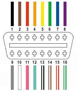
A standard OBD2 connector (OBD2C) has 16 pins. For this DIY OBD2 adapter, you’ll only need four:
- Pin 4: Chassis Ground (Orange wire)
- Pin 6: CAN High (J-2234) (Green wire)
- Pin 14: CAN Low (J-2234) (Brown with white stripe wire)
- Pin 16: Battery Power (Green with white stripe wire)
Constructing Your DIY OBD2 Adapter: A Step-by-Step Guide
Step 1: Prepare the OBD-II Cable
Remove the outer sheath and shielding from the OBD2C, exposing the individual wires. Separate the four necessary wires (orange, green, brown/white, green/white) and secure the remaining wires with a zip tie to prevent interference.
Step 2: Prepare the Wires for the 4-Pin Connector
Since the OBD2C wires (26 AWG) are smaller than the 4PC pins (22 AWG), you’ll need to “thicken” them. Strip about 3/8″ of insulation, fold the exposed wire over, and twist it. Slide a rubber seal (included with the 4PC) over each wire.
Step 3: Connect the Wires to the 4-Pin Connector Pins
Insert the exposed wire into the front prongs of the 4PC pin. Use needle-nose pliers to hold the wire in place if necessary.
Step 4: Secure the Connection (Soldering or Crimping)
- Soldering: Solder the wire to the pin for a solid connection. This is the recommended method.
- Crimping: If using a Molex crimping tool, crimp the connector over the wire. If you don’t have a crimping tool, carefully use needle-nose pliers to fold the prongs over the wire.
Step 5: Secure the Rubber Seal
Slide the rubber seal up between the back prongs of the pin and fold the prongs over the seal using pliers.
Step 6: Pair and Twist the Wires
Pair and twist the following wires together:
- Orange (Pin 4) and Green/White (Pin 16)
- Green (Pin 6) and Brown/White (Pin 14)
Step 7: Connect the Pins to the 4-Pin Connector Housing
Insert the pins into the 4PC housing in the following order:
- Slot A: Brown/White (Pin 14)
- Slot B: Green (Pin 6)
- Slot C: Green/White (Pin 16)
- Slot D: Orange (Pin 4)
Push each pin through the rear of the connector until you hear a click.
Step 8: Test Your DIY OBD2 Adapter
Connect your newly created DIY OBD2 adapter to your vehicle’s OBD-II port and your computer. Use diagnostic software to verify functionality by reading and clearing error codes.
Your DIY OBD2 adapter is now ready to use!